
My final project in high school welding was to build a can crusher. I took this as a challenge, and built an 8 cylinder boxer engine inspired can crusher. Suffice to say I got a good mark in the class.
My welding class' final project was to design and manufacture a metal can crusher of any kind. Me and a friend were talking about various designs, and he mentioned an: "Engine powered can crusher." While to him this meant using an engine to power the crushing mechanism, in my head images of the engine being the can crusher flooded to mind. Once I saw this design in my head, I knew I wouldn't be happy until I built it.
While I designed this project in Solidworks, the computer which had the CAD broke. Below is my first sketch of the system, which largely transferred to the final design. Essentially, the can would be dropped into the cylinder, where a motor would turn a crankshaft, moving the piston to crush the can, with the can dropping out the bottom.
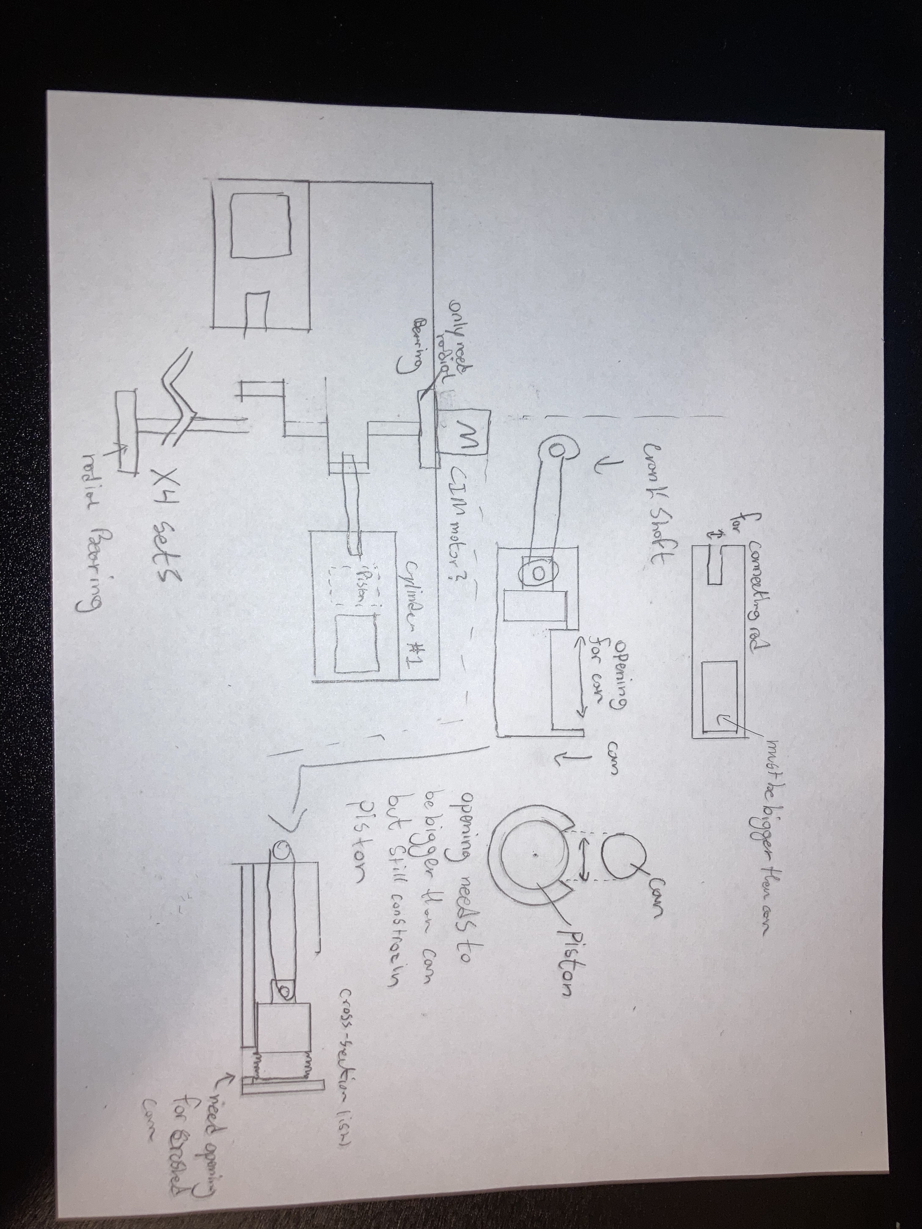
The major design considerations were the sizes of the piston and cylinder, as there needed to be a cutout section where the can would drop in, but since the piston pushed through this area the cutout still had to be small enough so that the piston would not fall out of the cylinder. This was simply a matter of designing large pistons, as the can diameter does not change. As well, latter on I realized I could fit two connecting rods for one section on the crankshaft, meaning I mirrored the design in the bottom left, instead of patterning it.
The main challenge of this project is in its manufacturing, and going through this process I learned many things, including the considerations of precision when welding is involved. The welding process used is aluminum MIG, as the project is done in aluminum. I did not have the best shielding gas for aluminum which resulted in some ugly welds, but this is a finer detail.
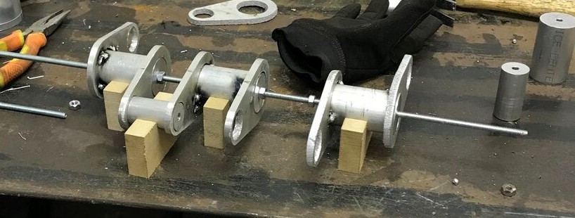
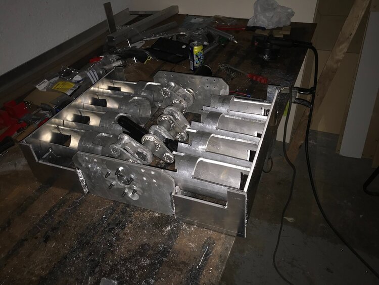
The crankshaft required a high level of parallelism and concentrism in its manufacturing. This was composed of round aluminum rods (larger diameter), which planar sections cut on my high schools plasma cutter to join the cylindrical sections. The aluminum cylinders were run on a lathe to have a hole, so that a small rod could be run through all sections to achieve the concentrism. As well, to make welding of this possible, MDF blocks were machined on my CNC router (See My Projects). The basic order of this process was: first weld the large cylinder to two flat pieces, using a small cylinder to ensure the two flat sections are aligned. From here setup the cylinders on the blocks, and align everything using the threaded rods, using nuts to space out everything. Lastly, weld the small cylinder sections to the flat pieces, and repeat until the crankshaft is complete. While this was not the ideal scenario, the crankshaft ended up being more than good enough for the project. This is probably because of the use of tack welds for alignment, followed by very patient and spaced out bead welds
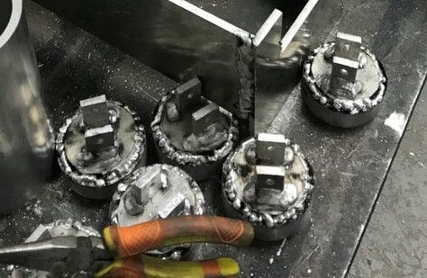
The pistons were composed of a very large diameter aluminum cylinder, with a section on top to connect to the connecting rod. A very key feature of manufacturing these, was the welding of the rectangular sections to a thin aluminum circle, and then welding this part to the top of the large piston. This was for two reasons: First it made it easier to weld the rectangular parts as I was closer to the table, and could use a 3D print for the alignment. But most importantly if I made a mistake welding these rectangles (which I did due to their size), I would not affect the more costly and limited in material piston. Welding these plates to the piston was easy as I could simply align them with a large vice grip and then weld.
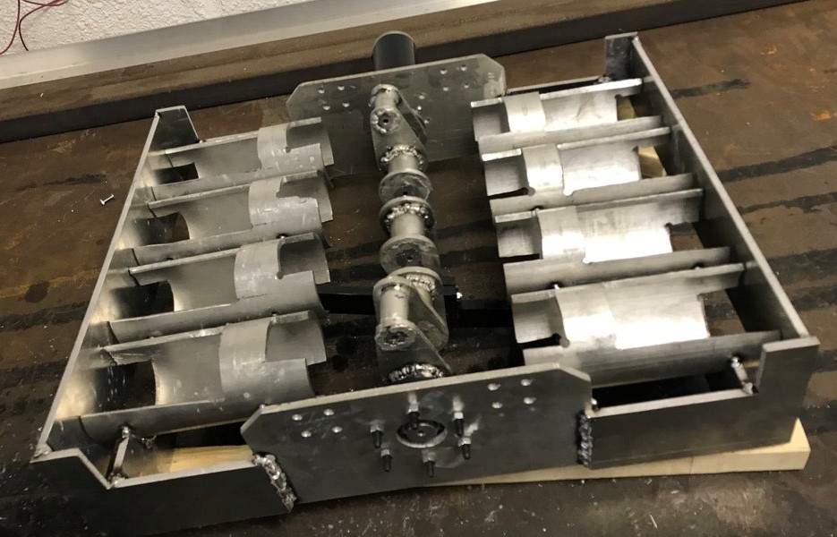
From here, the metal manufacturing was coming to a close, with the large assembly being the last and hardest thing to put together. First was the cylinder manufacturing which nearly gave me tinnitus (don't worry, I wore hearing protection.) Since I don't have fancy tube manufacturing equipment, I had to mark out the cuts for the cylinders by measuring and using a sharpie, followed by using a jigsaw to cut the cylinders. once this was done, It was a matter of joining the flat base sections which I cut on the plasma cutter. In terms of the welding, there was nothing particularly special. A series of ensuring perpendicularity or making simple jigs to make my job easier. The last step was joining the cylinders, which consisted of alignment and taking from the top, followed by flipping the assembly and running a full weld. This step is where most issues in the project came, which is a big thing I learned from this project. The welding of the cylinders caused the tight tolerance between the cylinder and piston to disappear, which almost completely destroyed this project. I talk about how I came over this in the following sections.
The connecting rods were machined out of HDPE on my CNC, as were the bearing blocks for the two crankshaft bearings. The motors were sourced from my robotics team and the fasteners came from McMaster-Carr. The cans were sourced from my love of Brisk iced tea.
As mentioned prior, after assembly I realized that the pistons often got jammed due to the welding. To solve this, I used automotive grease, trying to reduce friction inside the cylinder. In combination with sanding and filing, I managed to make one cylinder run out of the eight. You can see in the video below a can being crushed.
While there was much more I could have done to finished the project such as joining the back panel to the cylinders, increasing the opening size so that the can would drop through, and most obviously making all eight cylinders run, I did not. While I am not proud of stopping this project, it was simply getting too expensive, and looked like there would be lots of costs involved in fixing this. Overall the biggest lesson I learned was to be more piecewise in mechanical tolerance validation: If I were to have tested a piston with one cylinder, instead of welding them all at the same time, I would have saved myself time and effort, and also could have solved the problem before I made it.