
CAD parts are represented with a series of 2D sketches, followed by 3D geometric features. In this project I answer the question of if it is possible to use machine learning models to understand this data, by building a classification model.
Computer-Aided Design (CAD), has revolutionized the physical world around us, much like how machine learning has revolutionized the way we work with data. However, ML has barely been implemented into CAD, and its current research is limited to 2 dimensions, or simple geometry. Can I build a model which takes into account the sketches and features which are used to create this part, and build a model which can predict whether a part is a screw, nut, bearing or any other type of mechanical component.
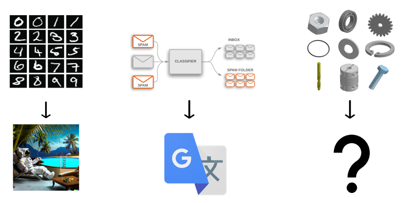
If we look at the history of ML, image process started with numeric classification with the MNIST dataset, whereas now we have models like DALL-E 2, which can generate images from prompts. Similarly in text, models which perform sentiment classification have guided our models to where we have neural translation in google translate. It seems logical to want to pursue mechanical part classification. Not due to this being an extremely important problem within CAD, but rather because the representations and models used to achieve this task can help inform us of the way we should represent CAD data for other machine learning models.
There are not any datasets which contain parametric CAD parts, let alone parts which are labelled. This is something we need.
We need a way for a model to understand these 3D parts. I extend a method for representing 2D sketches to be used for parametric CAD.
We need a model to do the classification task. Ideas and methods from sequence modeling are applied to our model.
Why build this if it can't tell the difference between a screw and a nut.
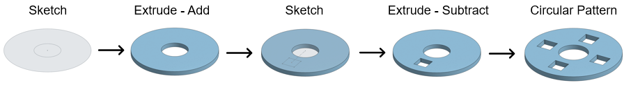
When we design in CAD, we think of it as a sequence of geometric operations which lead to a final geometry which is hopefully what we originally envisioned. In the first image below, we can see a simple part being generated by a 2D sketch, which is then extruded, a geometric operation which gives thickness. More operations are done such that we get our final geometry.
What we do not do is create parts by selecting a set of points, lines and faces representing our desired part. While there are many reasons for this to be the case, geometric primitives happen to also be easy to store as data, and as such most CAD datasets are composed of similar representations. We do not design this way, and as such using parametric representations are more powerful for ML, and for future uses of ML in CAD.
We need a parametric labeled mechanical component CAD dataset for this project. Parametric like discussed before meaning parts are defined using a sequence of geometric operations. Labeled meaning parts have broad categorical labels such as screw or nut, mechanical component meaning it is a standardized component; bearings, gears and all these kinds of parts go here. CAD meaning the parts exist in a CAD software such as Solidworks or Onshape. And dataset meaning we have lots of parts.

The current state of the art public datasets are the ABC net and Shapenet. These both are based on geometric primitives, discussed earlier. There does not exist a public dataset for what we need, thus we will need to make our own.
To obtain the data we need two things. First, a way to access part files from the internet, and second, a way to store CAD files, storing only their parametric definitions. For the first point, web-scrapping is the obvious solution. Parts are scrapped from McMaster-Carr, a well known mechanical component database, and Onshape, an online CAD software.
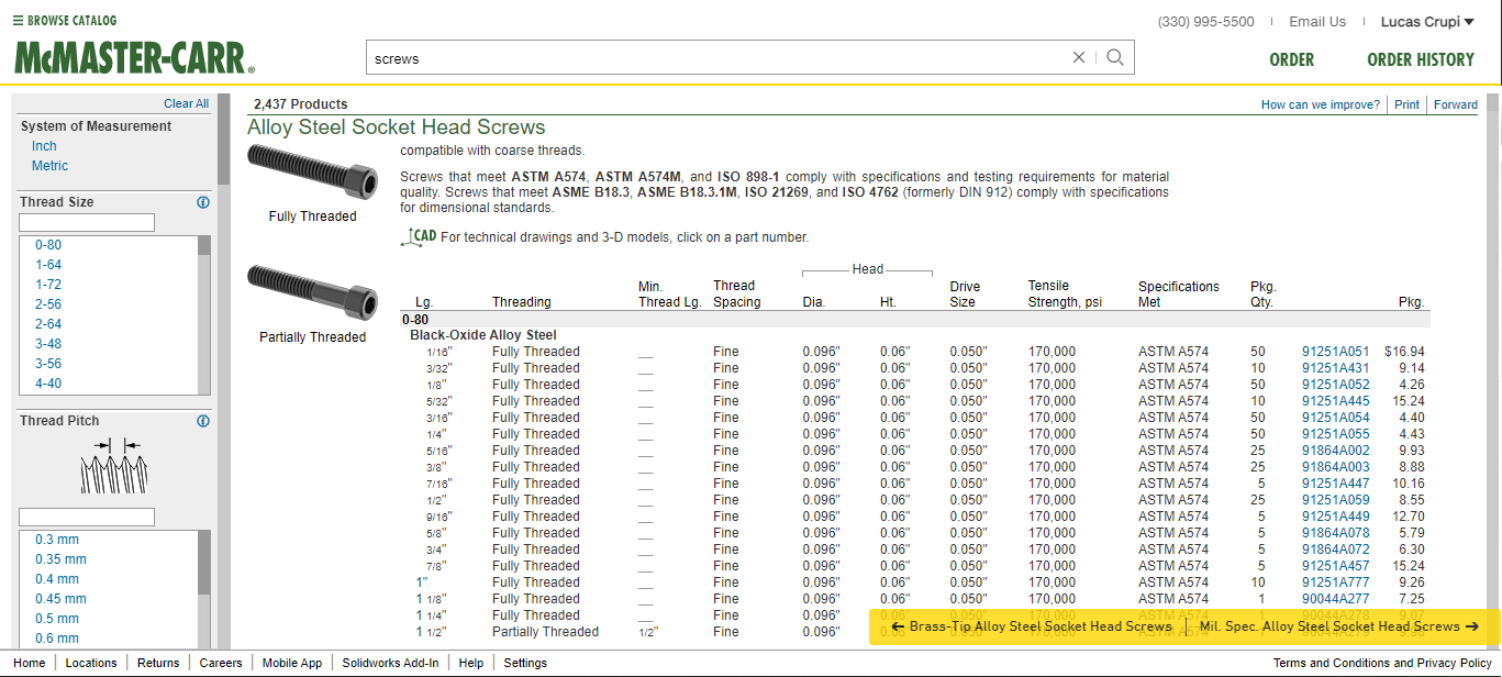
Scraping parts from McMaster-Carr is a relatively easy process due to their website design. Parts are well organized into categories and subcategories. For example, you can navigate to screws, and then from there Allen head screws and so on. Eventually once enough sub-categories have been selected, a page with links to specific parts is displayed, from which we can download the part files from the website. If you haven't already, check out www.mcmaster.com
From here it is simply a matter of writing a bot that can index each part link, and traverse through each, downloading the Solidworks CAD file as it does this. We then need to select links to these sub pages for each category of part, so that the web-scraper can download all of the parts from McMaster-Carr, while also knowing their category. When considering 30 categories of mechanical parts, there are an estimate 150,000 parts from McMaster-Carr we can download.
Halfway into scraping the nuts from McMaster-Carr, my IP and account was blocked from their website :(. We have since been in contact with McMaster-Carr to obtain access to their database. For now, we have ~10,000 screws and ~1,000 nuts to train our model. Once we gain access to more parts, I will post the updates!
The process of scraping Onshape is significantly different. Instead of a highly organized part catalogue, Onshape shows publicly created parts by their users, which are indexed by the name the user gives the part. We will soon see how even though Onshape hosts a large amount of parts in their public library, obtaining consistent categorical parts defined by their parameters is a big issue. First lets look at how we search for parts in Onshape. If we search screw, we will get a list of publicly created parts which contain screw in the name.
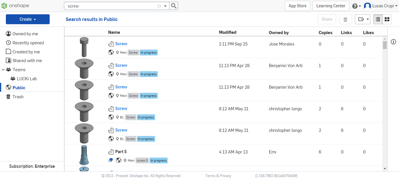
From here, we can write a bot that goes through this list (limited to 1000 results), and save the URL. Luckily for us, the Onshape API has the ability to interact with the part file, using the URL to connect to the part, meaning once the URL is saved we do not need to interact with the Onshape site. If we assume 1000 results for 30 categories, and 20 search terms per category we can assume an upper limit of 600,000 parts.
Problem #1
Each search term does not always return 1000 results, and sometimes there are no results. Even when we increase the number of search terms to the hundreds, this still accounts for roughly an 70% decrease in expected parts.
Problem #2
There are also instances where copies of parts exist which we can see in the image above with three of the same screws. While there are a few reasons for this, it ends up reducing our dataset size by roughly 50%.
Problem #3
Remember how these parts need to be parametrically defined and not just a set of geometric primitives... well most parts either are solely composed of geometric primitives, or are derived from them, resulting in another 70% loss in size to our dataset.
Problem #4
And to top it all off, Sometimes when someone labels their part a screw, it is not even a screw. Or the part is 10 screws lined up beside each other, all using one feature tree. This accounts for another 50% loss in size to our dataset.
Overall, we went from 600,000 parts to roughly 13,500 parts, or 450 parts per category. While this is still a large number, it is harder to train a decent model on this data. So for now, we won't be using Onshape data, however we might use it in the future to validate the model we build using McMaster-Carr.
Now that we have all of these parts, how will we take this data and feed it into the model that we build? We do two things. First, we take the 3D file from our CAD software, and convert the list of parameters into a JSON file, which is easy for file storage. From there we take this JSON file and convert the data into a sequence of 3 dimensional vectors called triplet vectors, which can be fed into our model.
This is a fairly tedious section, so I won't go into too much detail. Essentially for Solidworks, we use VBA to write a script which goes through each feature in the feature tree. It notes all the features parameters and the sketch from which is was created. All the data for all of its features is stored in a JSON file so that it is easy to then take out and use this parametric information in the future. This is similar for Onshape, however we use python to interface with their REST API, to obtain the same kind of information regarding the features making up a part. This part of the project likely took the most time, as it is a series of bug testing and fixing errors which arise due to either poor documentation, or a lack of functionality in the software's ability to give all the parametric information to a user.
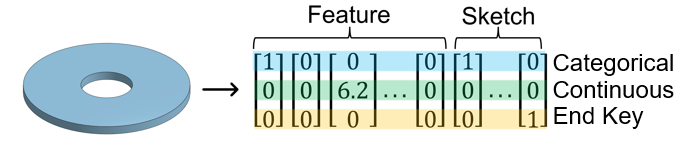
From these JSONs, we then convert them to these three dimensional vectors. Essentially, these vectors define the features and sketches in the part. Each vector can hold either a categorical piece of information, such as what type of feature something is, or what kind of entity something is in a sketch, or a continuous value, which could represent a point in space or the depth of a feature. There is also an end key for the end of a feature. Essentially, we build a consistent mapping from feature JSON to triplet, so that all of the information in the JSON is accurately represented in the triplet vector. This vector is what is put into our classification model.
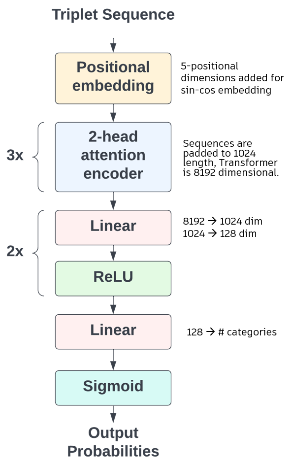
The classification model we build uses pre-established methods and ideas in sequence based machine learning., namely a set of attention encoders which then are processed by linear and non-linear layers. This is similar to what is seen in the BERT architecture. The model takes in the triplets, adds 5 dimensions to the vectors as well as positionally embeds them using standard sine-cosine embedding. This is followed by three, two-headed attention encoders, which look at the whole sequence, followed by the linear and non-linear layers. The outputs correspond to the models predictions. Cross entropy loss is used as the criterion for model evaluation.
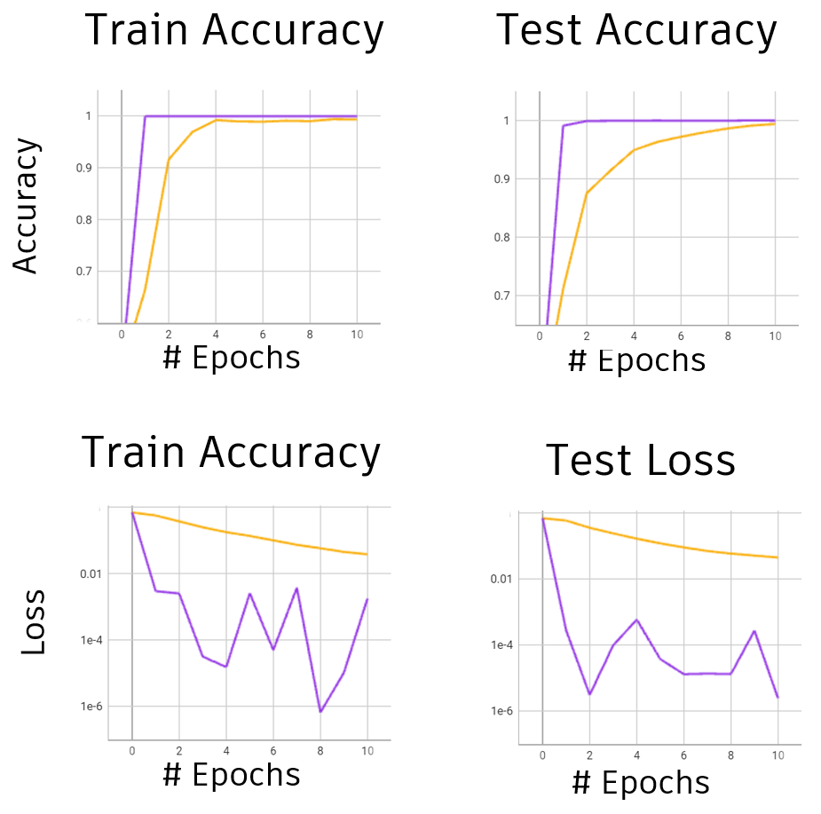
Since we currently only have a set of screws and nuts, we are limited to binary classification. Results for multi-category classification will be posted once the data is available. The model is trained using a 90/10 train test split, and is trained using stochastic gradient descent in yellow, and using ADAM in purple, using the default values of each in their respective paper(s). After ten epochs of training, the model achieves over 99% accuracy on both test and train, using both optimizers, and achieves a low loss. While it is true that a binary classification task is easier than multi-classification this still goes to show that the model is capable of learning to tell the difference between screws and nuts using their parametric information.
There are many possibilities of future research, and possible applications of this work. A few applications that can be derived directly from this work are organizational in nature. Examples are a built-in part classifier for assemblies that could put standard parts such as screws, or bearings into folders, or a search tool which could find similar parts given a search part. The more interesting side, which might have more applications in the future, is the generative side of machine learning. This work has proven that ML can be used for part classification, but extending this to using for example a generative adversarial network to generate new parts from scratch or optimize current parts given a goal is within the realm of possibility. One great example and application is a feature generator which could take information from a 3D model such as an STL or a point cloud, encode the geometry and then decode the features for a part. This would be a very useful application in the field of mechanical CAD.